Who am I?

Hello there. Welcome to my portfolio. Here you will find everything in relation to who I am, my work so far as an engineer.
To begin with, Hi, I am Rahul and I am a Manufacturing Engineer with Criswell Singapore.
Before that, I was a mechanical design engineer with more
than 3 years of experience with a Singapore
based startup, where I have designed, built and fabricated 3 working HVAC prototypes. Alongside, I have
acquired key insights of daily-running of a startup in a
feedback driven
development processes.
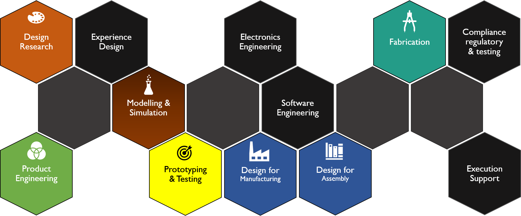
I possess multidisciplinary skills in Industrial Design, Product Development, and Design for Manufacturing and Assembly. I begrudgingly admit, I am now a specialist-generalist, with honed skills in mechanical design and prototyping.
I will allow my portfolio to showcase and present in-depth visualizations of the work I have done over the past few years.
Portfolio
Over the years through my career, I have found myself continuously learning new things, adapting and getting better at them.
This "portfolio" depicts all the things which I have mastered or rather gotten better at. I started as an Aerospace Engineer with skills in Aircraft Designs, Computational Fluid Dynamics and flow visualizations. But given how things rarely ever pan out the way you would think, I now find myself fully versed in different domain of engineering. Whereby:
- I am now fully appreciative of the actual manufacturing process, instead of just the design stage. Understanding to work with various GD&Ts, manufacturing nuances and more, have emboldened the designer in me.
- I have learned that phase of gathering design requirements is just as important as the design itself.
- I understand the full picture of hardware based product development with key focus on Design for Manufacturing and Design for Assembly. Otherwise, the cost borne in terms of hours and money is too high.
- I am highly aware of crucial processess in production stage such as Sourcing parts, managing various timelines, tracking how parts are made, forming partnerships with OEMs, small scale vendors, which ultimatelty make or break a product.
There are more things which I have learned and contributed to, but the following inexhaustive presentation should give the right idea. I have the content separated based on categories which should give a cleared picture.
- All
- Manufacturing
- Product Design
- Research & Development
- Testing & Validation
Manufacturing and Production
Some highlights showcasing how a part is produced in manufacturing setting. Taking CAD models, programming them and validating using backplots before turning to manufacturing.
Timelapse of CAD being drawn according to the specifications.
Simulation of the programmed toolpaths based on machining specifications from the shop floor and tools available. *Simulation provides a quick way to ensure the tools are complaint of things like safe retracts, tool hits or finishing issues.
And, also making sure operations are in right order and not skipped over, including:
- Facing
- Contouring
- Roughing
- Finishing
- Drill and Hole making
Backploting to view and validate the nc-code genereated by the software. This is to ensure conversion through CAM software is legible by the machine controller.
5-axis machining
Many parts, either due to the manufacturing process or the lack of complexity can make do with 3-axis machining process. However, for parts like the one here, saves time and effort using a 5-axis machining process. Although 4-axis machining process can be used, but that entails removing the setup when 3-axis operations are done and setting up again and 4-th axis to finish it off, introducing more variables which can adversely effect tight tolerancing.
Here, the simulation highlights all the generated toolpaths and how the tool approach changes for different sides of the part. Do note that the simulation is keeping part stationary and moving the tool. Machine simulation can be done as well, but I find this easier to diagnose issues.

CAD with cusps and curved surfaces.
Simulation highlighting different and unique toolpaths and selection of tools for certain parts to account for smooteher surfaces and different tolerance requirements. Here, alongside flat-end mills, ball nose end mills were used.

Just the toolpaths highlighted to show different operations and how the rapid movements, retracts and cutting takes place in the process.
Simulation and the actual part for comparison. The part is made of Ultem thermoplastic to be used as a manifold for high temperatures and pressures. Sealing the manifold meant the part needed to be precise. This part was reject due to tolerances being off.
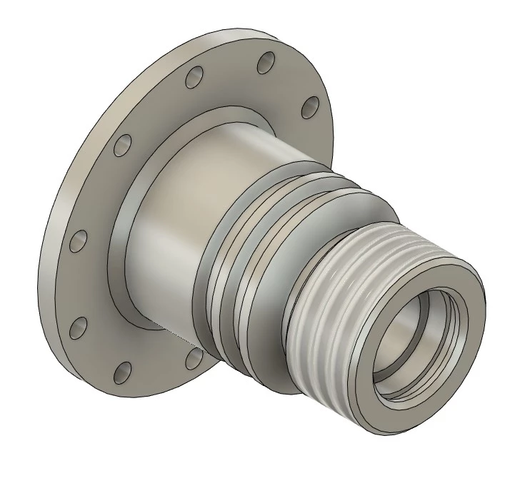
CAD for lathe operations
Parts with cylindrical features are best made on lathes. Although certain 4-axis and 5-axis methods can achieve the similar shape, however, for maintaining higher tolerances it's often preferrable to use lathe. Not just that it is faster, but has low probablity of human incurred issues.
Simulation of lathe operation showcasing the difference in approach to cutting using different tools to rough, thread, bore and separate the part from the stock.
Product Design
I am fascinated by industrial designs, and do believe I have a knack for the drafting up quick designs. Althouh most often, I have driven to design something based on work, but every now and then I have drawn some designs. Here are some of the drawings, CAD, animations, app designs, concept work etc., showcasing my work.

Swiveling desk mounting
This concept was made to showcase the design issues a client had. Essentially, the hinge caused the board to hit seat arm while folding. I made the changes such the issues are alleviated.
Animation through Fusion 360, to demonstrate the fact that the collision should no longer occur based on the modifactions discussed with the client.
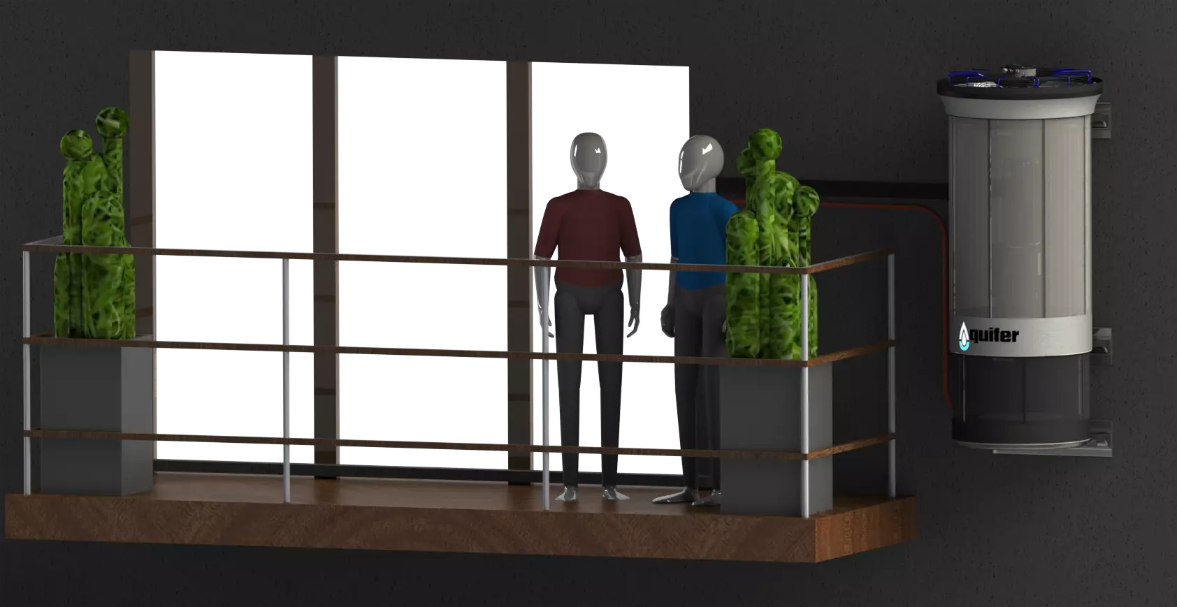
Product concept demonstration
Mounting a product in housing environment to showcase how it sits with the environment. This was the first product I worked on with Aquifer/Disruptive Thermodynamics.
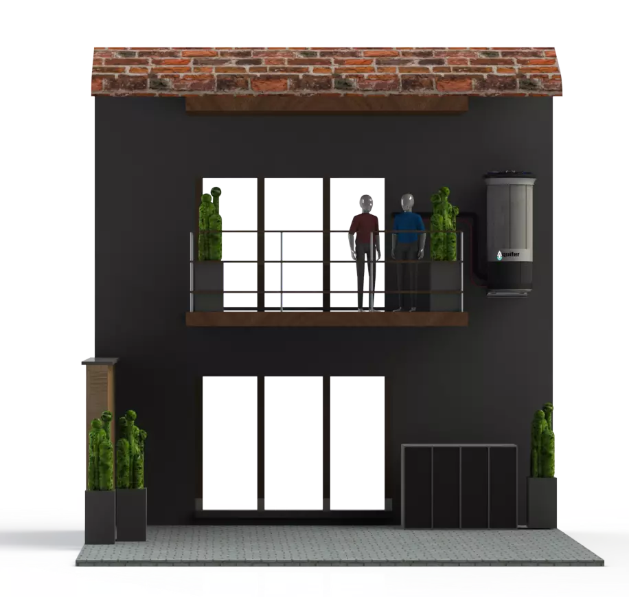
Full width view of the a house, where the product is installed on the wall alongside the balconey.
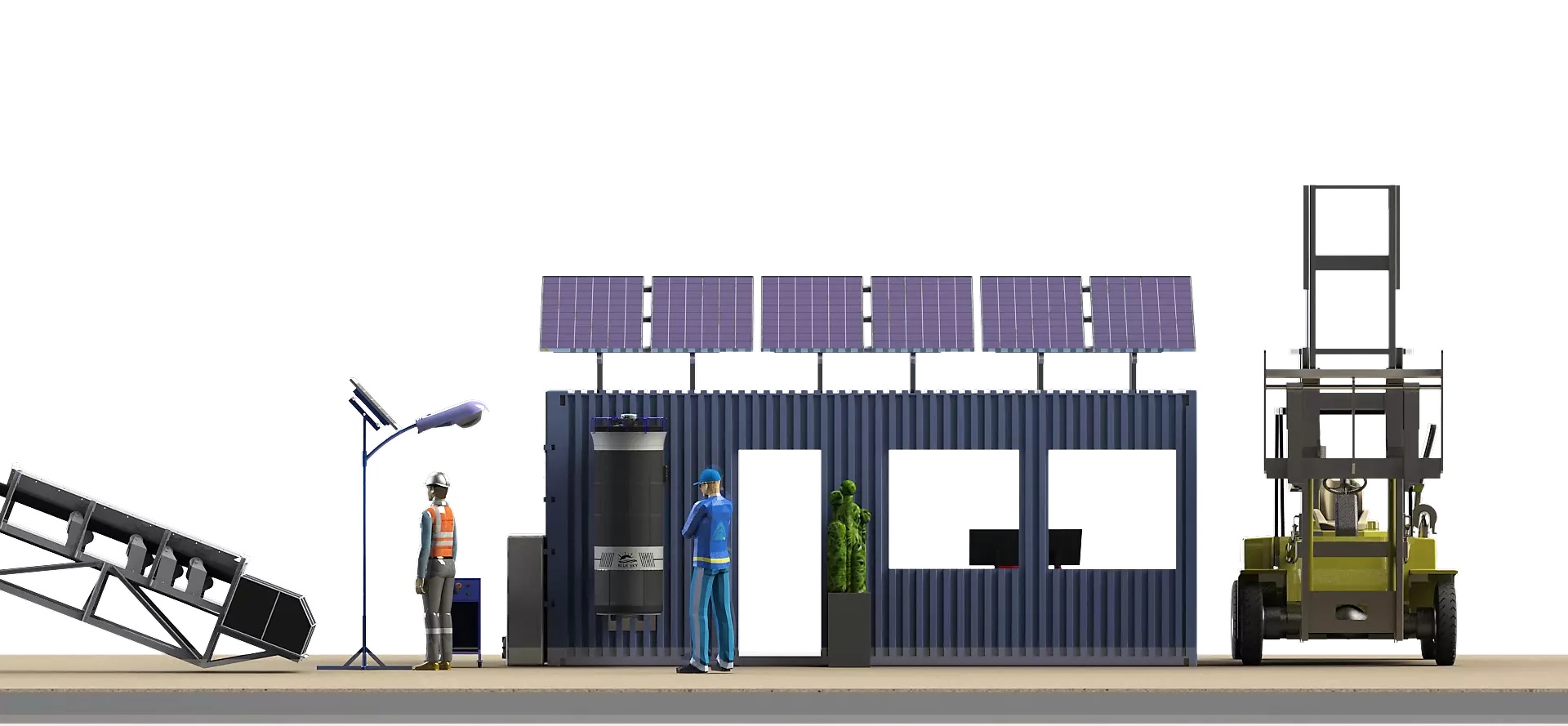
This was designed to showcase how the same product can work in an construction environment, where by the product is mounted on the shipping container office.
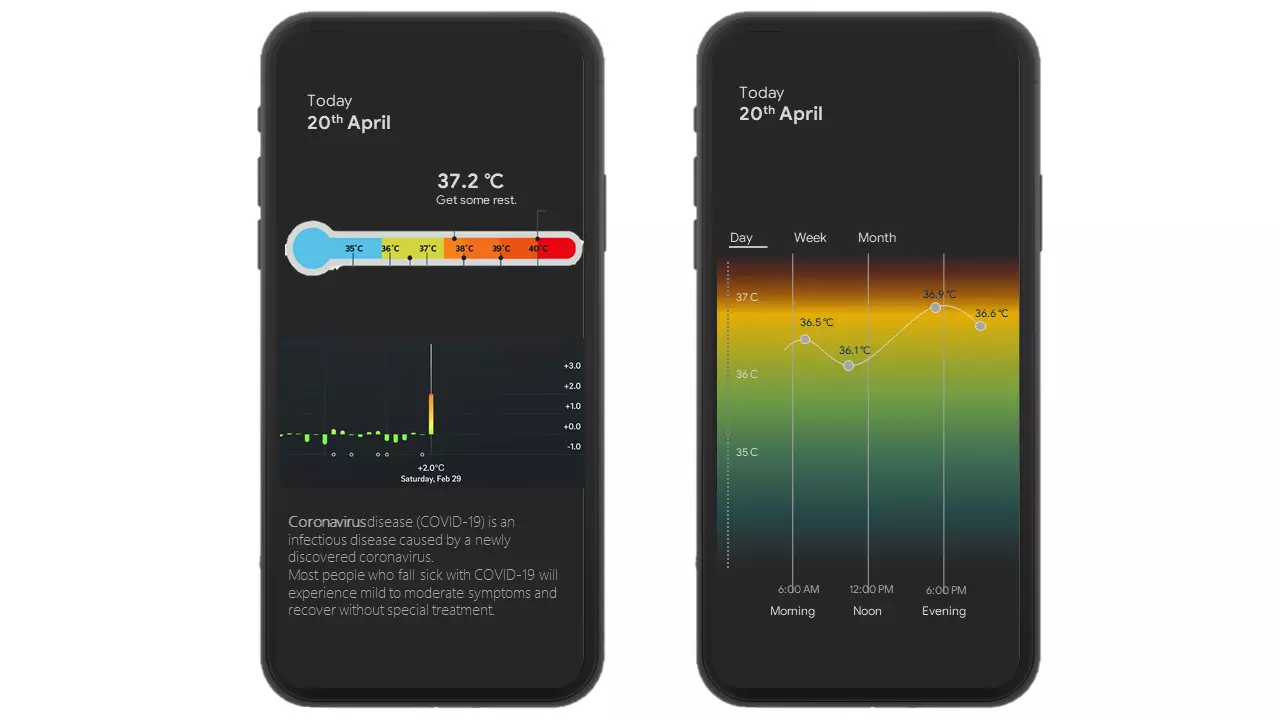
App Mockup for monitoring body temperature.
Drafting a mockup to see how a dedicated temperature monitoring app would look like.

Evaluating varous UX/UI elements and dark themes along side. Making it easier for a user to interact.
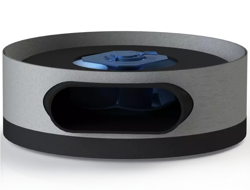
Conceptual Model for a dual fan HVAC
A concept that would be mounted on a ledge, is light weight and is aestheticly pleasing.

Evolution of handheld thermometer, called Mini-IR
Working with my colleagues to develop a economic smart thermometer which logs temeprature for each use.

Different concepts developed which were feasible to manufacture on a budget.
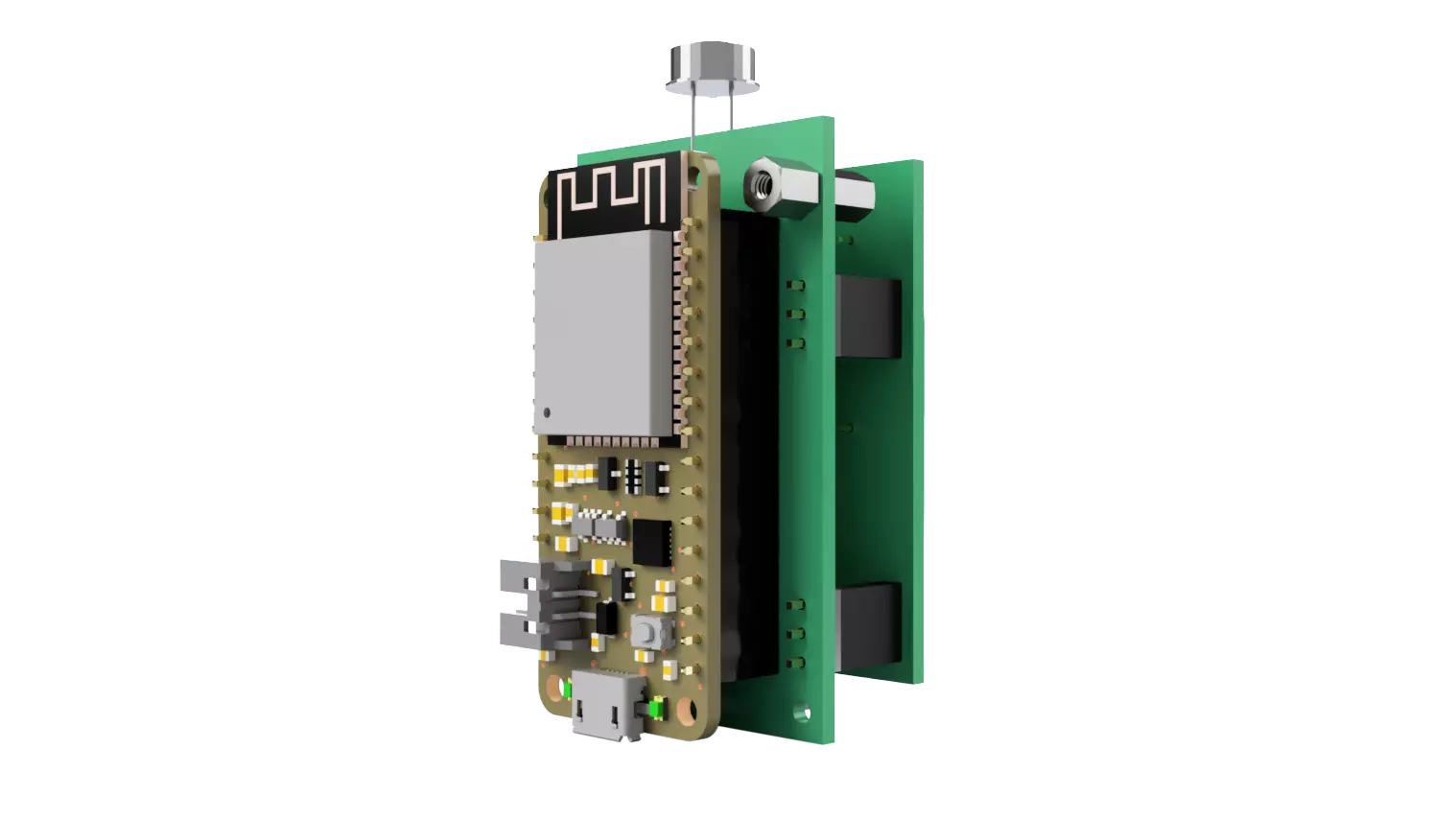
Internal assembly of components of Mini-IR

HVAC Demonstration in a mining camp
Visualizing the number of units required to cool the rooms in a mining camp.
Volute Designs
Designing volute based on the product requirements, to ensure perfromance is not lost with housing this compact.
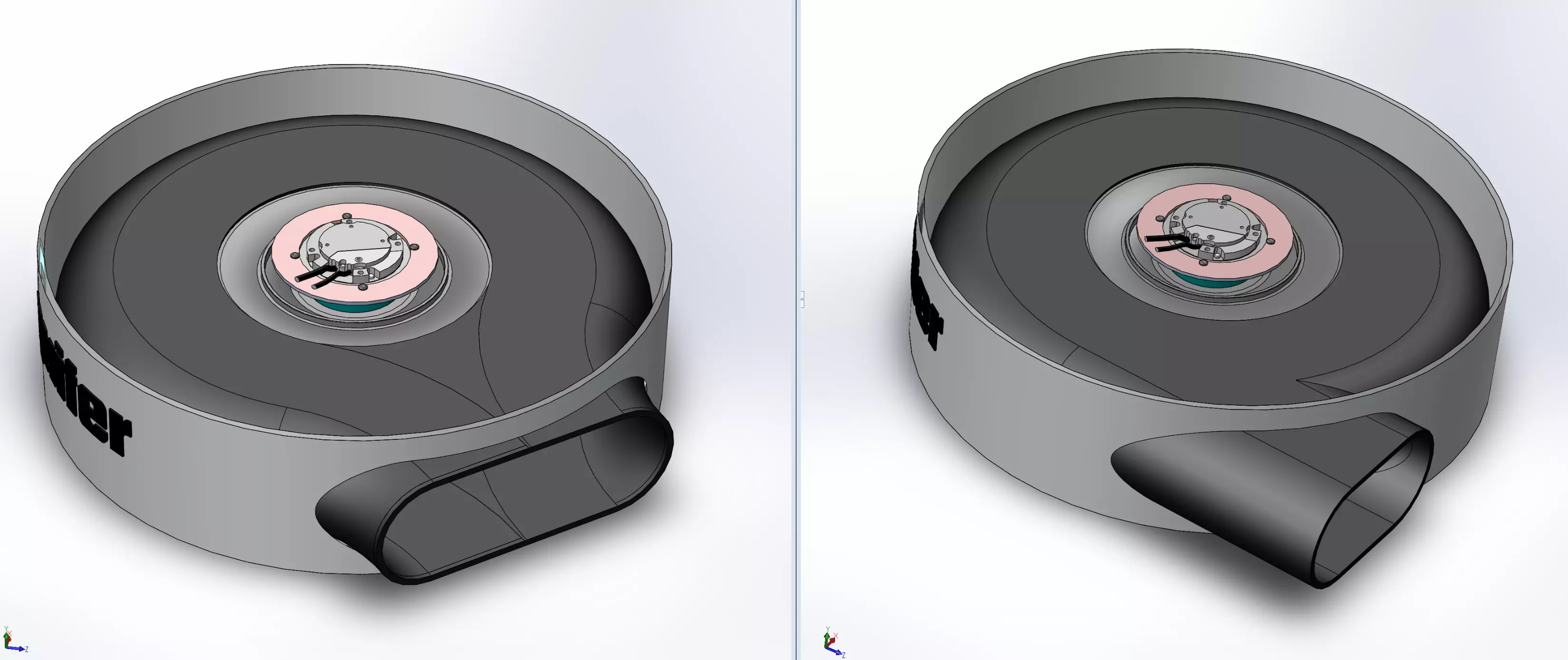
Going through different configurations to settle with the optimal perfromance with minimum back pressure through CFD.
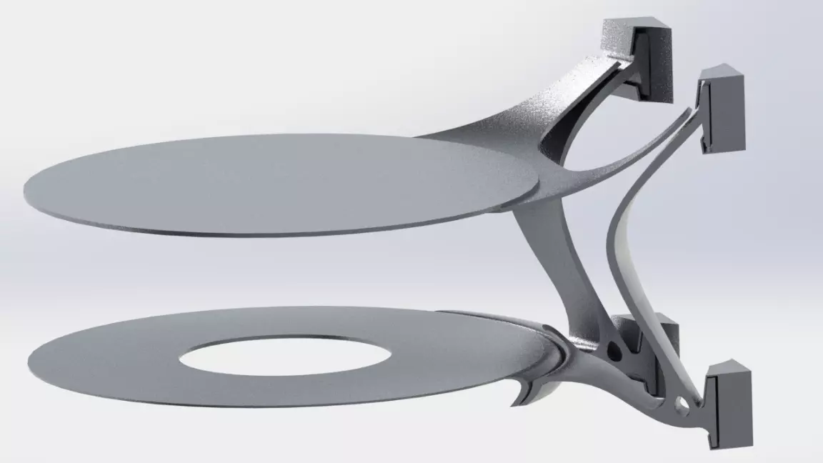
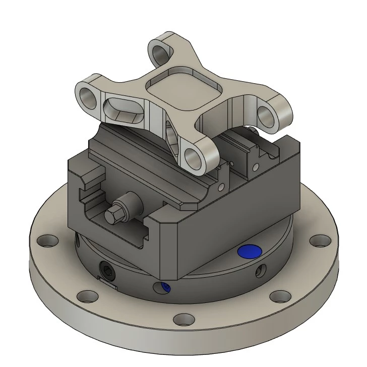
Cantilever mounting mechanism for a 160kg componet.
The design's purpose was to distribute load across 4 separate mounting locations on the wall to ensure consisten load distribution.
Research and development
Through out my masters and my job, I have used CFD, FEA simulations to conceptualize, ideate and produce parts which help realize the CAD into reality. Here are some of those simulations and other elelments showcasing my work.
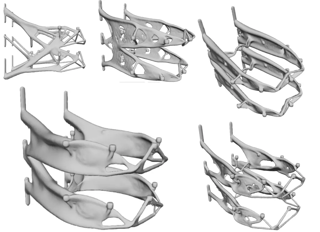
Generative designs of a mounting bracket
Going through several iterations to identify and visualize the mounting points based on set constraints.
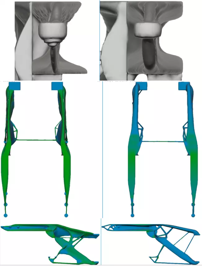
Comparitve generative design
After convergence of certain design aspects, next is comparison of designs, to distinguish weight saving characteristics and ease of manufactuing.
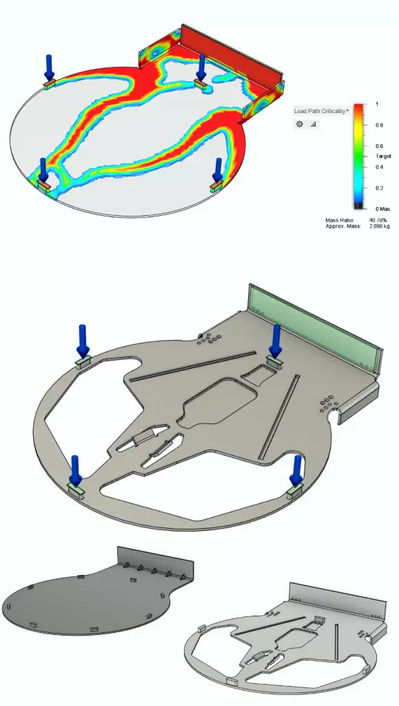
Load Path analysis for weight saving.
As the original part is too heavy, for integration with the rest of the machine, it is critical to reduce weight, whilst simultaneously ensuring machinablity. Appropriate loads are applied and regions are marked for removal, making sure the changes don't have high impact on a set Safety factor.
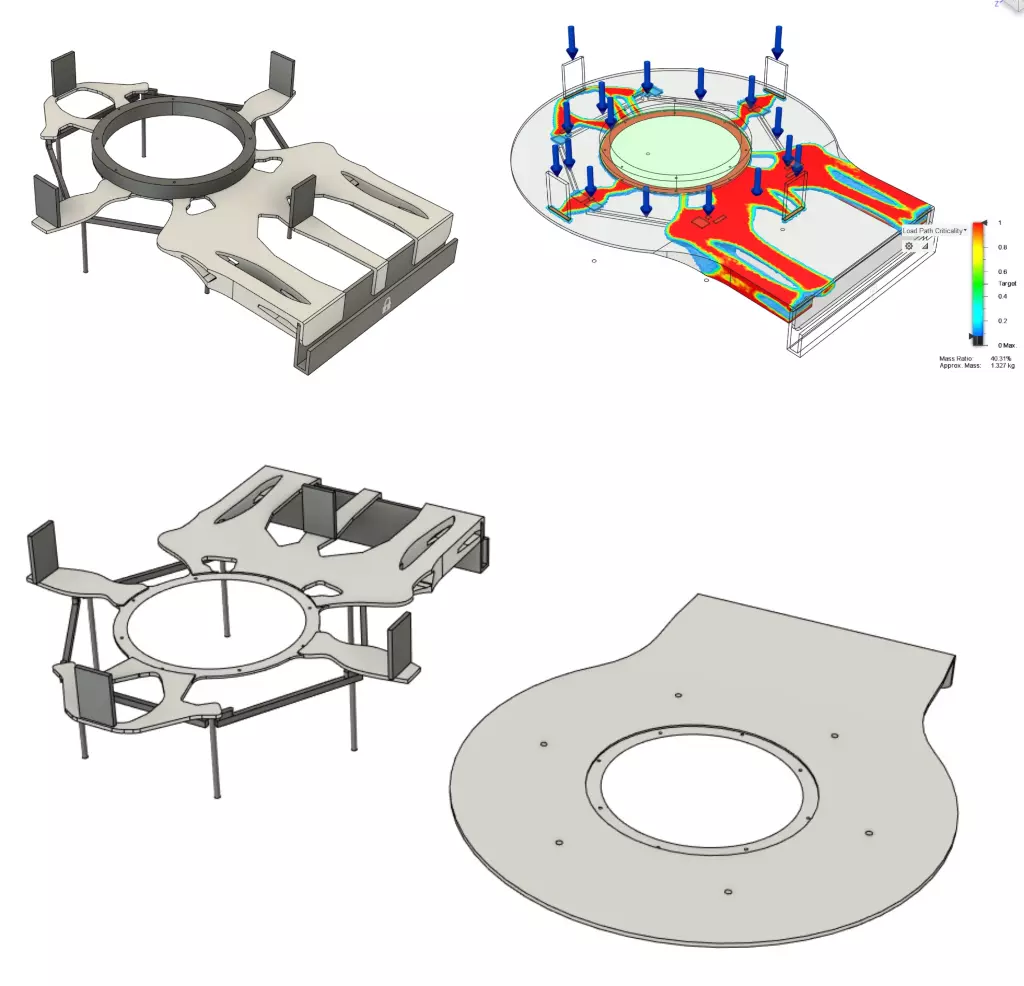
Weight reductions for another part.
For certain, not so load bearing parts, load analysis allowed for higher material reductions, maintaining the set safetyfactor.
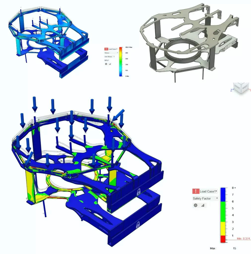
Full assembly load analysis
Becomes cruicial to analyse and test for full assembly context, as load acting on it can change. Here, it is a good example of how, on their own the parts were complaint of Safety factor set, however, in conjuction with assembly shows newer failure points.
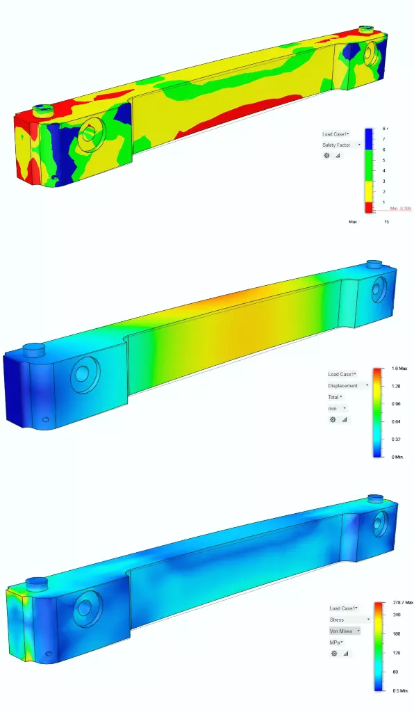
Stress, deflection analysis of a manifold
For a part under load, material selection and overall design becomes a crucial point in design. Based on applied constraints and materials selected, it becomes evident that this part would fail.

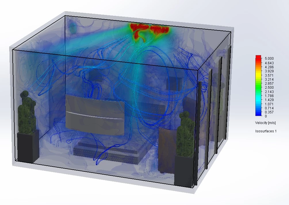
Designing and setting up a test room for HVAC performance
Designed a test room with different material properties to understand influence of draft from the HVAC, windows heat transfer and presence of an open boundary.
Side view of the test room depicting the influence of heat transfer through the window. The velocity spheres showcasing not just the reflection of the particles, but change in velocity due to different surfaces.
Another test room visualization
Coverage of air draft across the room and its impact on a person.
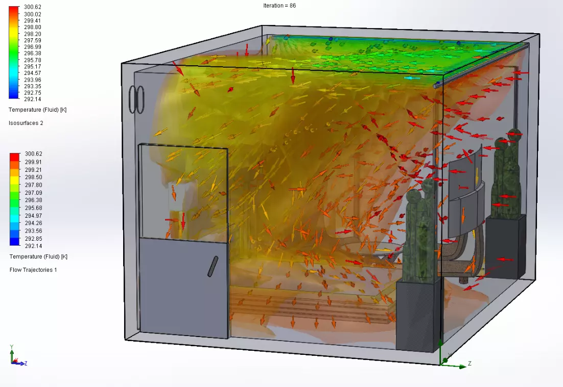
Thermal visualization of air as it exits the duct and spread across the room.
Initial turbulence created when the HVAC is turned on, and showcases the impact of HVAC position in a room.
Flow simulation of a 3-way refrigerant splitter. For the application, knowing the upstream value dictates the velocity distributed through the splitter. As the part is custom made, the part is modified till the appropriate downstream values are achieved.
Back pressure analysis
To understand the full impact of a custom volute, flow is simulated to find out the backpressure increase due to restricted sections in the design.
Back pressure analysis of an axial fan
As the machine was being incluenced by the outwash of an OEM nozzle, a custom shorud was made and the outwash was analysed.
Similarly, the tip vortices are simulated to see the impact on static pressure on overall system.
Full assembly analysis flow distribution.
Studying the influence of a custom diffuser over flow distribution through the system.
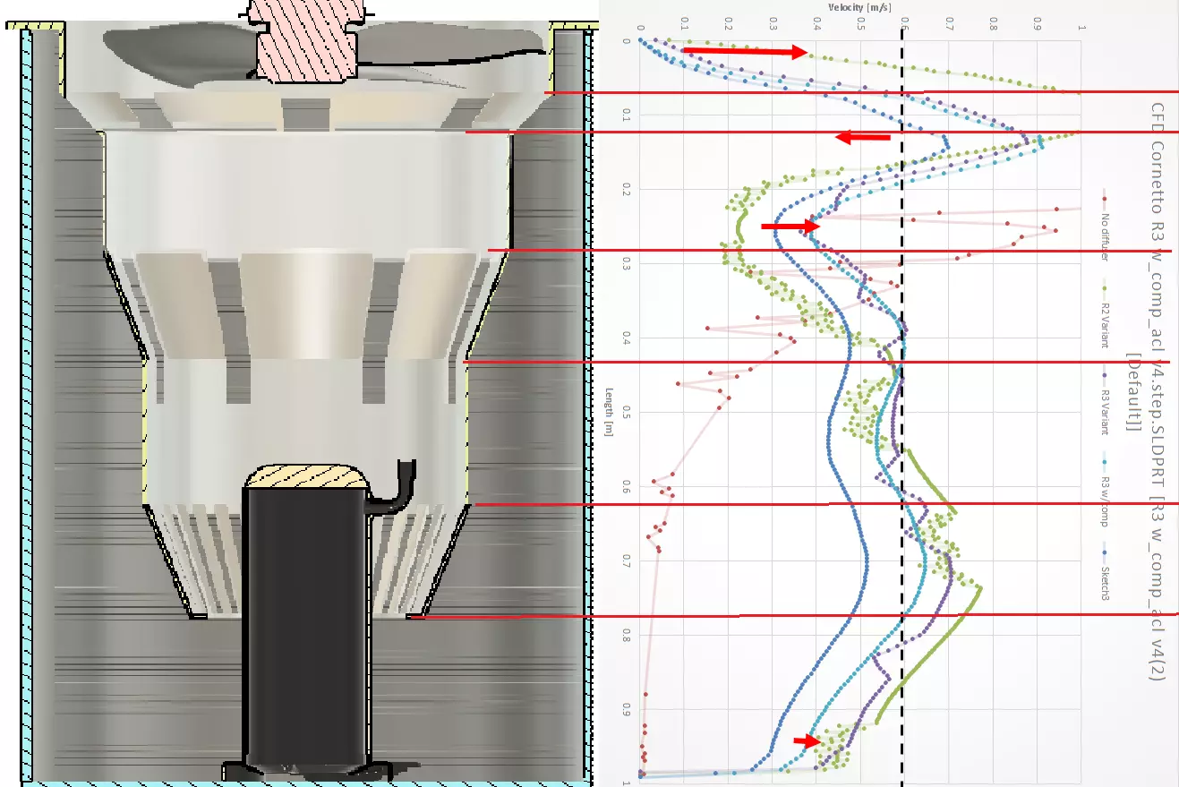
Plotting the distribution along the height of the machine to adapt the diffuser for optimized parameters.
2-D analysis of heat exchanging tubes in a controlled environment.
Analysis of temperature change due to the presene of a cold low pressure refrigerant flowing through a series of tubes.
Testing and validation
After the design and fabrication stage, the focus is on testing the concepts and validating the solutions to ensure correct intended operations. Here are some of the things I am versed with processes involving thermal analysis, audio spectrograms, creating BOMs, part tracking, task tracking and testing methodolgies to evaluate a concept.
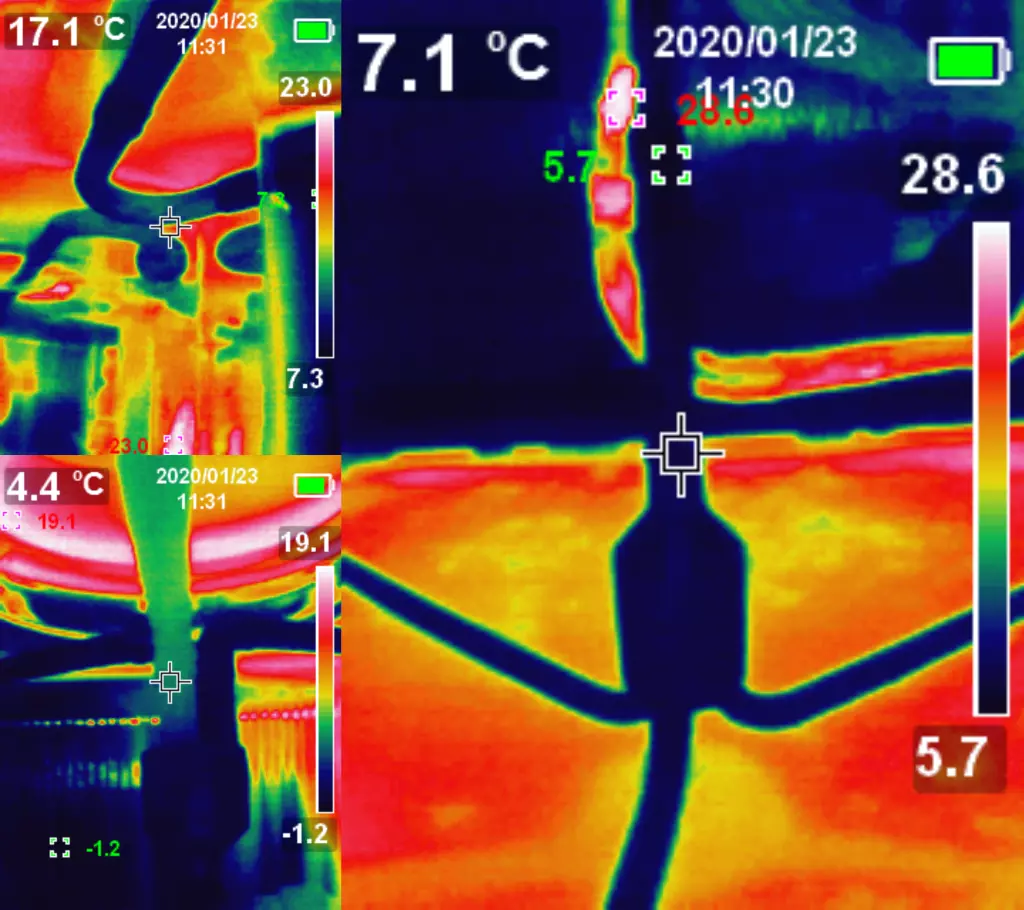
Thermal images of a condenser section
Diagnosing flow distribution issues due to improper flow accross a flow splitter. It was quite evident that one section was hoter than the remain two, implying flow restrictions inside.
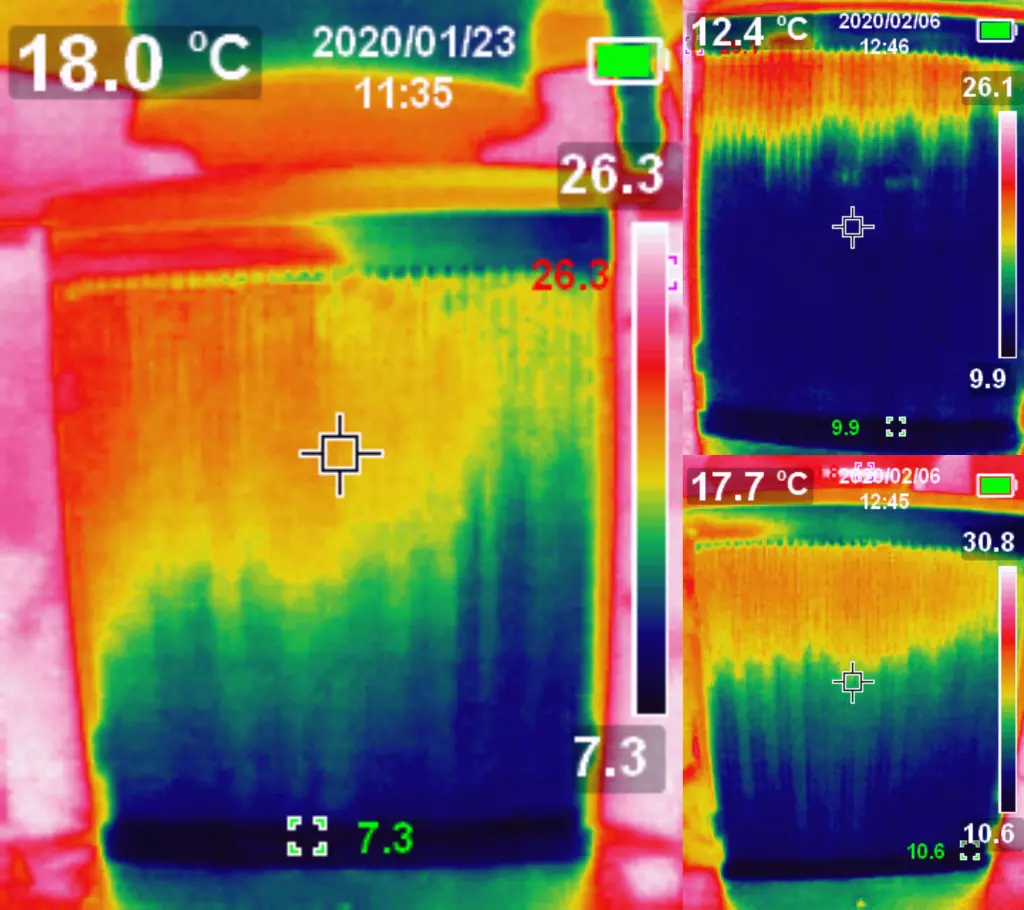
Consequently, the heat exchangers lost performance and incurred more temperature losses, reducing the efficiency of the hole system
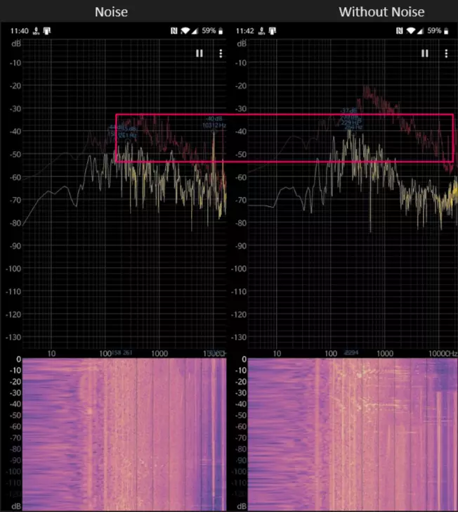
Audio Spectogram analyis
Analysing different acoustics of a compressor due to presence of electrical noise present in the system impairing the compressor through the process.
Development of Diagnostic performance monitor
Understanding the intricacies of tuning the PID driver expansion valve in the system. Excessive osciallations are bad for the system, given the system never achieves sustained efficiencies.
Tuned PID's impact on the system, with the osciallations reduced significantly.

Sensor data comparison for flow with and without diffuser
Full system is integrated with various pressure and temeprature sensors to understand the full picture of air and refrigerant passing through the machine.
The data is plotted to visualize impact that the presence of a diffuser has on the system.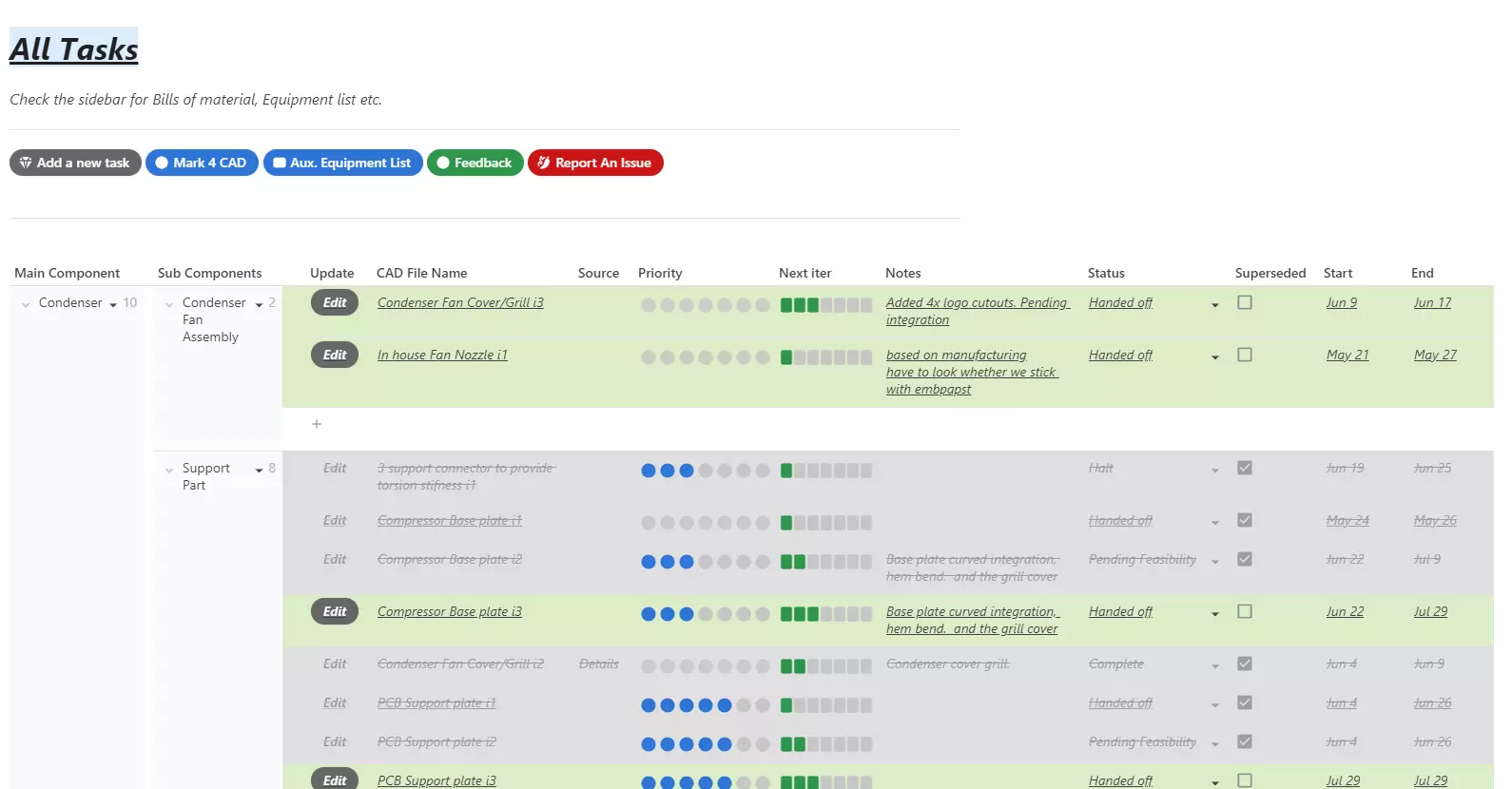
Built a task tracker integrated with CAD design and vendor relations.
Built the application on a platform called Coda.io, which tracks design progress, RTM status and assigned priorites based on parts availability.

Filtered tasks viewer
For rest of the team, to break down key details, such that progress is easily conveyed to all the key people.

Using Coda.io for product timeline
Created a project timeline, such that the work has accurate scope of time and effort required to achieve the goal. This includes design, fabrication, testing and prototyping phases for one product.

Bills of material
Created a custom Bills of material template on Coda.io which is flexible such that it allows for not only the overview of all the components and their properties, but fabrication times, lead times, weight estimations, design version, revisions, status of manufacturing, source etc.

Generated Auxiliary equipment list using the same platform
For small parts to be sources directly through various small vendors, created and tracked auxiliary list for price estimations, time and cost savings.
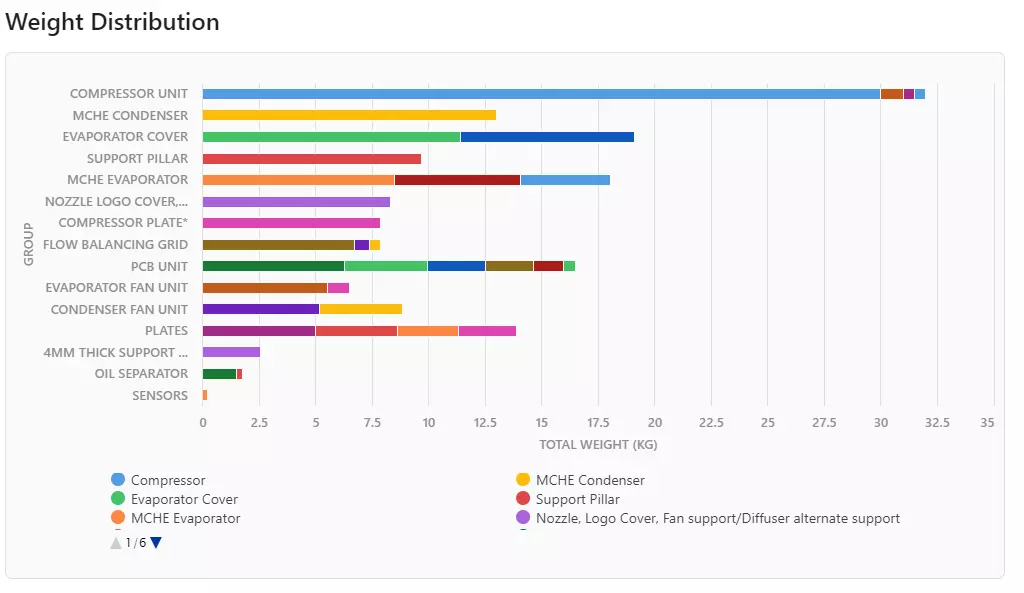
Weight distribution of the final product
Accurately determining the overall weight distribution before the physical build to give a general scope of the machine in a physical scene.